- 您现在的位置:买卖IC网 > Sheet目录3890 > PIC16C717T-E/SS (Microchip Technology)IC MCU OTP 2KX14 A/D PWM 20SSOP
2002 Microchip Technology Inc.
DS41120B-page 123
PIC16C717/770/771
12.8
Time-out Sequence
On power-up, the time-out sequence is as follows:
First PWRT time-out is invoked by the POR pulse.
When the PWRT delay expires, the Oscillator Start-up
Timer is activated. The total time-out will vary based on
oscillator configuration and the status of the PWRT.
For example, in RC mode with the PWRT disabled,
there will be no time-out at all. Figure 12-6, Figure 12-
and
depict
time-out
sequences on power-up.
Since the time-outs occur from the POR pulse, if MCLR
is kept low long enough, the time-outs will expire. Then
bringing MCLR high will begin execution immediately
(Figure 12-8). This is useful for testing purposes or to
synchronize more than one PICmicro microcontroller
operating in parallel.
Table 12-5 shows the RESET conditions for some spe-
cial function registers, while Table 12-6 shows the
RESET conditions for all the registers.
12.9
Power Control/STATUS Register
(PCON)
The Power Control/STATUS Register, PCON, has two
status bits that provide indication of which power-up
type RESET occurred.
Bit0 is Brown-out Reset Status bit, BOR. The BOR bit
is unknown upon a POR. BOR must be set by the user
and checked on subsequent RESETS to see if bit BOR
cleared, indicating a BOR occurred.
Bit1 is POR (Power-on Reset Status bit). It is cleared on
a Power-on Reset and unaffected otherwise. The user
must set this bit following a Power-on Reset.
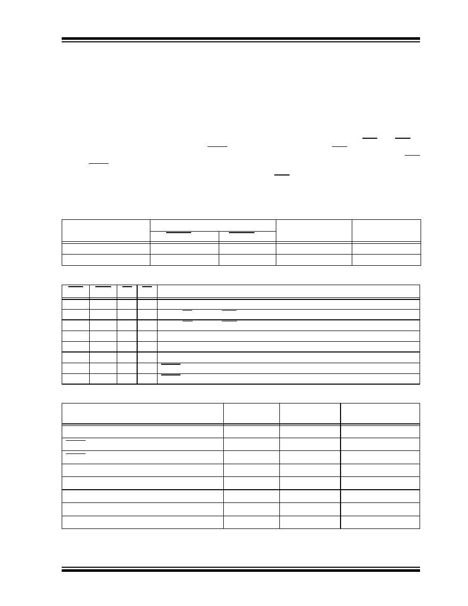
TABLE 12-3:
TIME-OUT IN VARIOUS SITUATIONS
TABLE 12-4:
STATUS BITS AND THEIR SIGNIFICANCE
TABLE 12-5:
RESET CONDITION FOR SPECIAL REGISTERS
Oscillator Configuration
Power-up
Brown-out
Wake-up from
SLEEP
PWRTE = 0
PWRTE = 1
XT, HS, LP
TPWRT + 1024TOSC
1024TOSC
TPWRT + 1024TOSC
1024TOSC
EC, ER, INTRC
TPWRT
—
TPWRT
—
POR
BOR
TO
PD
0x
1
Power-on Reset
0x
0
x
Illegal, TO is set on POR
0x
x
0
Illegal, PD is set on POR
10
1
Brown-out Reset
11
0
1
WDT Reset
11
0
WDT Wake-up
11
u
MCLR Reset during normal operation
11
1
0
MCLR Reset during SLEEP or interrupt wake-up from SLEEP
Condition
Program
Counter
STATUS
Register
PCON
Register
Power-on Reset
000h
0001 1xxx
---- 1-0x
MCLR Reset during normal operation
000h
000u uuuu
---- 1-uu
MCLR Reset during SLEEP
000h
0001 0uuu
---- 1-uu
WDT Reset
000h
0000 1uuu
---- 1-uu
WDT Wake-up
PC + 1
uuu0 0uuu
---- u-uu
Brown-out Reset
000h
0001 1uuu
---- 1-u0
Interrupt wake-up from SLEEP, GIE = 0
PC + 1
uuu1 0uuu
---- u-uu
Interrupt wake-up from SLEEP, GIE = 1
0004h
uuu1 0uuu
---- u-uu
Legend: u = unchanged, x = unknown, - = unimplemented bit read as '0'.
发布紧急采购,3分钟左右您将得到回复。
相关PDF资料
PIC16LC770T-E/SO
IC MCU OTP 2KX14 A/D PWM 20SOIC
PIC16C771T/SO
IC MCU OTP 4KX14 A/D PWM 20SOIC
PIC16LC717T-I/SS
IC MCU OTP 2KX14 A/D PWM 20SSOP
PIC16C717T/SS
IC MCU OTP 2KX14 A/D PWM 20SSOP
PIC16LC770T-I/SO
IC MCU OTP 2KX14 A/D PWM 20SOIC
PIC16LC771T-E/SS
IC MCU OTP 4KX14 A/D PWM 20SSOP
PIC16C771T-E/SS
IC MCU OTP 4KX14 A/D PWM 20SSOP
PIC16LC771T-I/SO
IC MCU OTP 4KX14 A/D PWM 20SOIC
相关代理商/技术参数
PIC16C717T-I/SO
功能描述:8位微控制器 -MCU 3.5KB 256 RAM 16 I/O RoHS:否 制造商:Silicon Labs 核心:8051 处理器系列:C8051F39x 数据总线宽度:8 bit 最大时钟频率:50 MHz 程序存储器大小:16 KB 数据 RAM 大小:1 KB 片上 ADC:Yes 工作电源电压:1.8 V to 3.6 V 工作温度范围:- 40 C to + 105 C 封装 / 箱体:QFN-20 安装风格:SMD/SMT
PIC16C717T-I/SS
功能描述:8位微控制器 -MCU 3.5KB 256 RAM 16 I/O RoHS:否 制造商:Silicon Labs 核心:8051 处理器系列:C8051F39x 数据总线宽度:8 bit 最大时钟频率:50 MHz 程序存储器大小:16 KB 数据 RAM 大小:1 KB 片上 ADC:Yes 工作电源电压:1.8 V to 3.6 V 工作温度范围:- 40 C to + 105 C 封装 / 箱体:QFN-20 安装风格:SMD/SMT
PIC16C71T-04/SO
功能描述:8位微控制器 -MCU 1.75KB 36 RAM 13 I/O 4MHz SOIC18 RoHS:否 制造商:Silicon Labs 核心:8051 处理器系列:C8051F39x 数据总线宽度:8 bit 最大时钟频率:50 MHz 程序存储器大小:16 KB 数据 RAM 大小:1 KB 片上 ADC:Yes 工作电源电压:1.8 V to 3.6 V 工作温度范围:- 40 C to + 105 C 封装 / 箱体:QFN-20 安装风格:SMD/SMT
PIC16C71T-04I/SO
功能描述:8位微控制器 -MCU 1.75KB 36 RAM 13 I/O 4MHz Ind Temp SOIC18 RoHS:否 制造商:Silicon Labs 核心:8051 处理器系列:C8051F39x 数据总线宽度:8 bit 最大时钟频率:50 MHz 程序存储器大小:16 KB 数据 RAM 大小:1 KB 片上 ADC:Yes 工作电源电压:1.8 V to 3.6 V 工作温度范围:- 40 C to + 105 C 封装 / 箱体:QFN-20 安装风格:SMD/SMT
PIC16C71T-20/SO
功能描述:8位微控制器 -MCU 1.75KB 36 RAM 13 I/O RoHS:否 制造商:Silicon Labs 核心:8051 处理器系列:C8051F39x 数据总线宽度:8 bit 最大时钟频率:50 MHz 程序存储器大小:16 KB 数据 RAM 大小:1 KB 片上 ADC:Yes 工作电源电压:1.8 V to 3.6 V 工作温度范围:- 40 C to + 105 C 封装 / 箱体:QFN-20 安装风格:SMD/SMT
PIC16C71T-20I/SO
功能描述:8位微控制器 -MCU 1.75KB 36 RAM 13 I/O RoHS:否 制造商:Silicon Labs 核心:8051 处理器系列:C8051F39x 数据总线宽度:8 bit 最大时钟频率:50 MHz 程序存储器大小:16 KB 数据 RAM 大小:1 KB 片上 ADC:Yes 工作电源电压:1.8 V to 3.6 V 工作温度范围:- 40 C to + 105 C 封装 / 箱体:QFN-20 安装风格:SMD/SMT
PIC16C72/JW
功能描述:8位微控制器 -MCU 3.5KB 128 RAM 22 I/O RoHS:否 制造商:Silicon Labs 核心:8051 处理器系列:C8051F39x 数据总线宽度:8 bit 最大时钟频率:50 MHz 程序存储器大小:16 KB 数据 RAM 大小:1 KB 片上 ADC:Yes 工作电源电压:1.8 V to 3.6 V 工作温度范围:- 40 C to + 105 C 封装 / 箱体:QFN-20 安装风格:SMD/SMT
PIC16C72-04/SO
功能描述:8位微控制器 -MCU 3.5KB 128 RAM 22 I/O RoHS:否 制造商:Silicon Labs 核心:8051 处理器系列:C8051F39x 数据总线宽度:8 bit 最大时钟频率:50 MHz 程序存储器大小:16 KB 数据 RAM 大小:1 KB 片上 ADC:Yes 工作电源电压:1.8 V to 3.6 V 工作温度范围:- 40 C to + 105 C 封装 / 箱体:QFN-20 安装风格:SMD/SMT